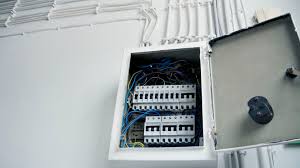
Guide to Buying An Electrical Circuit Breaker
A large safety concern in both residential and commercial buildings is overloading or causing a short circuit within the electrical circuit. The component that is used to prevent this from occurring is an electrical circuit breaker. A circuit breaker is used to protect the circuits within your home or business. If a fault is detected within the circuit the system will cause a break in the electrical current flow causing the system to come to a halt.
The type of circuit breaker you choose to purchase will depend on a number of things. In order to purchase the correct electrical circuit breaker you need to clearly understand your needs and the needs that will be placed on the system. When purchasing a new or refurbished circuit breaker, your electrical supplier will discuss several factors with you to help you select the best breaker for your needs.
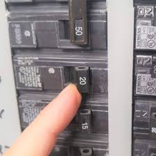
The first thing an electrical supply company will ask you about when purchasing a circuit breaker is the amount of electricity that will be flowing through the breaker. The voltage load of the circuit breaker you choose will depend heavily on the equipment that will be used on the circuit as well as the overall load of electricity that will run through the circuit.
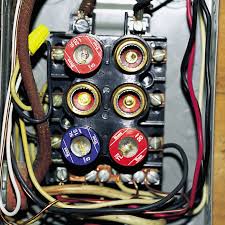
There are three main voltage categories when it comes to circuit breakers. Low voltage circuit breakers are used in residential electrical circuits. A low voltage electrical circuit breaker works best in households and can handle a max load of 1000 volts. Medium electrical circuit breakers are suitable for buildings and office settings. A medium breaker is good for use when voltage requirements are between 1000 and 72,000 volts. Large electrical circuit breakers handle voltage loads upwards of 72,000. Large breakers are typically used for high voltage power transmission lines.
The next consideration of various circuit breakers is the mounting style. The two main components are fixed mounted circuit breakers and removable mounted circuit breakers. A fixed mounted circuit breaker is mounted so that it cannot be removed without removing the main connections and mounting supports. A removable mounted circuit breaker has two parts, the base and the actual breaker. The base is bolted and hardwired to the frame where is the breaker is plugged into the base. This system can be replaced without having to rewire
Electric Circuits
Suppose that you were given a small light bulb, an electrochemical cell and a bare copper wire and were asked to find the four different arrangements of the three items that would result in the formation of an electric circuit that would light the bulb. What four arrangements would result in the successful lighting of the bulb? And more importantly, what does each of the four arrangements have in common that would lead us into an understanding of the two requirements of an electric circuit?
The activity itself is a worthwhile activity and if not performed before, one ought to try it before reading further. Like many lab activities, there is power in the actual engagement in the activity that cannot be replaced by simply reading about it. When this activity is performed in the physics classroom, there are numerous observations that can be made by watching a class full of students eager to find the four arrangements
Light Bulb Anatomy
Once one group of students successfully lights the bulb, many other lab groups quickly follow suit. But then the question emerges as to what other ways that the cell, bulb and bare wire can be arranged in such a manner as to light the bulb. Often a short light bulb anatomy lesson prompts the lab groups into a quick discovery of one or more of the remaining arrangements.
A light bulb is a relatively simple device consisting of a filament resting upon or somehow attached to two wires. The wires and the filament are conducting materials that allow charge to flow through them. One wire is connected to the ribbed sides of the light bulbs. The other wire is connected to the bottom base of the light bulb. The ribbed edge and the bottom base are separated by an insulating material that prevents the direct flow of charge between the bottom base and the ribbed edge. The only pathway by which charge can make it from the ribbed edge to the bottom base or vice versa is the pathway that includes the wires and the filament. Charge can either enter the ribbed edge, make the pathway through the filament and exit out the bottom base; or it can enter the bottom base, make the pathway through the filament and exit out the ribbed edge. As such, there are two possible entry points and two corresponding exit points.
The Requirement of a Closed Conducting Path
There are two requirements that must be met to establish an electric circuit. The first is clearly demonstrated by the above activity. There must be a closed conducting path that extends from the positive terminal to the negative terminal. It is not enough that there is simply a closed conducting loop; the loop itself must extend from the positive terminal to the negative terminal of the electrochemical cell. An electric circuit is like a water circuit at a water park. The flow of charge through wires is similar to the flow of water through the pipes and along the slides at a water park. If a pipe gets plugged or broken such that water cannot make the complete path through the circuit, then the flow of water will soon cease. In an electric circuit, all connections must be made and made by conducting materials capable of carrying charge. As the cell, bulb and wire experiment continues, some students explore the capability of various materials to carry a charge by inserting them in their circuit. Metallic materials are conductors and can be inserted into the circuit to successfully light the bulb. On the other hand, paper and plastic materials are typically insulators and their insertion within the circuit will hinder the flow of charge to such a degree that the current ceases and the bulb no longer lights. There must be a closed conducting loop from the positive to the negative terminal in order to establish a circuit and to have a current.
Electric Circuits Review
A water ride at a water park is analogous to an electric circuit. First of all, there is an entity which flows – water flows in a water park and (in conventional terms) + charge flows in an electric circuit. In each case, the fluid flows spontaneously from a high energy location to a low energy location. The flow is through pipes (or slides) in a water park and through wires in an electric circuit. If the pipes or the wires are broken, then there can be no continuous flow of fluid through the circuit. A complete loop is required to establish the circuit.
This flow of fluid – whether of water or charge – is possible when a pressure difference is created between two locations in the circuit. In the water park, the pressure difference is the difference in water pressure created by two locations of different heights. Water flows spontaneously from locations of high pressure (high altitude) to locations of low pressure (low altitude). In an electric circuit, the electric potential difference between the two terminals of a battery or energy source provides the electric pressure which presses on charge to move them from a location of high pressure (high electric potential) to a location of low pressure (low electric potential).
Energy is required to move the fluid uphill. In a water park, a water pump is used to do work upon the water in order to raise it from the low height back up to the high height. The water pump does not supply the water; the water which is already in the pipes. Rather, the water pump supplies the energy to pump the water from the location of low energy and low pressure to the location of high energy and high pressure. In an electric circuit, the battery is the charge pump which pumps the charge through the battery from the location of low electric potential energy (the – terminal) to the location of high electric potential energy (the + terminal). The battery does not supply the electric charge; the charge is already in the wires. The battery simply supplies the energy to do work on the charge in pumping it uphill.
The flow of water at a water park is analogous to the flow of charge in an electric circuit. The rate at which charge moves past a point on a circuit as measured in Coulombs of charge per second (or some comparable set of units) is known as the current. In our analogy, the fluid which flows is water and the rate at which the fluid passes any given point is the current.
Electric Circuit Studio
Electric Circuit Studio (ECStudio) is a set of tools used for building electronic circuits, SPICE simulation, and calculation of circuits. These tools are complemented by the information center containing resources, connector pinouts and interactive book explaining basic electrical theorems, laws and circuits. It is a useful application for all electronics hobbyists, students, or other people with an interest in electronics.
Schematic editor and SPICE simulator allow easy creation of circuit diagrams and SPICE analysis of the created circuits. ECStudio simulator is focused on visual representation of simulated results, such that simulated voltages and currents can be placed elsewhere in the circuit, as a text or graph. Moreover, the magnitude and polarity of voltages and currents can be represented by visual indicators, so you can check the results quickly. All results can be additionally displayed on the top plot, where they can be explored using two cursors
DC, AC and Transient analyses are supported. The simulation can be run repeatedly (in Transient analysis) and results can be displayed consecutively with a user controlled speed (in all analysis types), or all simulation results are displayed immediately. When the results are shown consecutively, you can control parameters of circuit elements by the seek bar and see the change of results in real time
The application supports two modes: Normal and Restricted. The Restricted mode differs from the Normal mode in that the size of the drawing canvas is restricted to the size of the circuit, elements cannot be inserted, moved, rotated, flipped or deleted, and the undo, redo, saving and opening circuits are not allowed. This mode is intended to be used only for simulation of circuits.
The application uses the shared storage to store circuits, pictures, models, screenshots, exported and log files. This storage is usually internal memory, or it can be an external SD card. The location of the application directory is Documents/ElectricCircuitStudio (or Documents/ECStudio for the users who installed ECStudio versions below 2.2). Note: the Pictures subdirectory is deprecated, as the Pictures can now be inserted through the Picture Selection window
A sequence to develop ideas about simple electrical loops
Electrical loops are rather pervasive, as they are such a convenient way of getting jobs done. That’s because electrical loops are good at powering things, and because that power can be controlled. So it makes some sense to start off by looking at the jobs that electrical loops can do for us in the lived in world, and to move from there to creating and varying loops for themselves.
There is some practical difficulty in investigating mains electricity: not helped by the fact that many mains plugs and sockets have three terminals. Therefore we’d suggest not trying to make too careful a link between these early explorations and later work with making loops. ( There is a clear connection, but it’s not simple – you can see more in the SPT: Electricity and energy topic.)
There is however plenty of simple practical activity that can be used to get children off on the right track in thinking about electrical loops. As much of this involves making things there are opportunities for strong links with other parts of the curriculum.
A sequence for developing the idea
This is a rather short sequence focusing on electrical loops, once we have established the pervasiveness of electricity.
We think it’s very helpful to think in terms of loops, as all electrical circuits are made of loops. Finding the loop, breaking the loop, making the loop and choosing what to put in the loop are all useful activities they get children thinking along the right lines. Each loop needs thinking of as a whole if you are to understand it and that’s a further advantage of thinking about electrical circuits in terms of complete loops